Find the way
I made this project together with Luca as the final project in our apprenticeship. It started back in fall 2015. You could either do a project by your own or just go ordinary to your classes. So I think we all know where this is going.
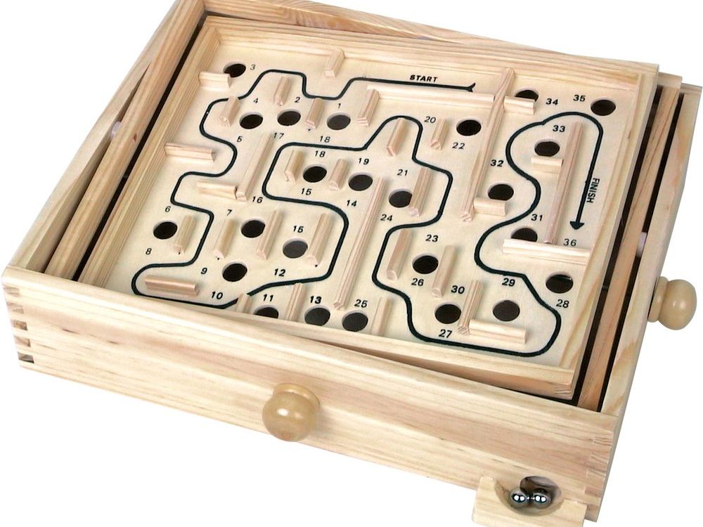
Everyone knows the wooden labyrinth, where you have to try to get the ball from the start to the finish. Our goal was to achieve this as an autonomous system. You can place the walls as you like and after starting the system, the fastest route is calculated and then driven independently.
First, a picture of the current labyrinth is made with help of the camera mounted on top, a matrix is generated from it, which is then processed with a specially developed algorithm. This gives you the route to be followed. Now, with the help of the camera, the current position of the ball is continuously analyzed, from which the PID controller regulates the inclination of the plate in accordance with the target position. The ball is driven autonomoulsy through the maze until it finally reaches the goal position.
At this point in time, such a project was a pretty big deal for us. We "only" were in apprenticeship but had to work with highly complex technologies. Fortunately, everything worked out just fine and the project was up and running. Not only did we have a awsome final project, we also won at Schweizer Jugend forscht in spring 2016. This is a national competition where all the young scientists can present their projects and the best ones win and some get even some spezial prizes.
General conceps
The basic idea was to automate the well known wooden maze. We found various uniaxial variants under the term “PID Ball”. This is basically a rail that is attached to a joint in the middle and is moved depending on the position of the ball. Under the terms "Ball on Plate" we found other projects with plates that are also attached to a joint in the middle and have two actuators on the sides. The actuators on all the platforms we found were controlled via model servos. The position is determined with a camera and the control is carried out accordingly. As i was working at this time in a company which produces linear actuators (to this things more furter down, we wantet to realize it with those, as nobody did this before. To begin with, we defined some important requirements:
- Use linear motors as actuators with a stable mounting.
- The whole construction should have very small tolorances.
- The support arm that holds the camera should be easy to disassemble.
- The entire electrical unit should be compact and in one unit.
- The complete structure should be easy to transport.
First steps
First Prototype
To begin with we had to try out some different ideas. As we never did something like that before, first we draw a couple of sketches and then we put some materials we had lying around together and got startetd. We had two ideas. One with a bearing in the middle and two actuators and an other one with four actuators, one on each edge. The reason for the second one was, it would be possible to keep the ball constantly on the same hight. Just the inclination of the plate would change. With the first variant, the force and acceleration acting on the ball would differ depending on its position.


Second Prototype
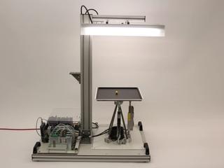
After some experimenting, we decided to go with the two actor option. The Problem with the different force and acceleration turned out to be just fine and the control logic and mechanical construction was a lot easier this way. As you can see, this version already looks pretty similar to the final one. And it worked out pretty well. But as it turned out, it still wasn't stable enough. The universal joint, which was a normal one which you can find in every toolbox, appeared to have a pretty big tolorance. We didn't think about this at the beginning. Also, under full speed, the whole construction was shaking, even the arm with its camera. As you can imagine, for a high precision with computer vison like this one something like that was unacceptable.


Final version
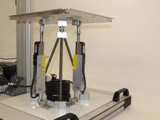
So we had to back to the drawing board. Most importantly, everything had to be really stable. The entire system was previously drawn in CAD. A detailed CAD drawing was created for each component. My friend Luca is really talented when it comes to mechanical constructions and CAD. He designed a new bracket with four legs to reach maximal stability.
This was far the most complex parts, which received the four threaded rods and takes over the connection between the base plate and the labyrinth. Here the difficulty was the compact size and to drill the threads correctly. In order to find an optimal angle, we had to make a compromise. The best possible angle would have been 45 degrees. To implement this, the four legs of the system would have been to be placed extremely far apart. To get a good space and stability ratio, we agreed on a 20 degree angle. This still gives us enough stability in relation to the space requirement. Even the most complicated parts were quickly drawn in CAD, but the difficulties only became apparent during production. We had to find this out the hard way. We also carried out simulations in CAD, in which the components were tested for sufficient stability. Some of the parts initially had sufficient stability, but when implemented, the requirements could not be achieved due to the tolerances. The entire degrees of freedom, which result from the ball joints and the universal joint, were simulated in CAD to guarantee the freedom of movement of the system. It had to be ensured that the linear motors can retract completely.


Here you can see the final bracket. This one turned out to work pretty well. In the title image you can see the complete final version. At least for the mechanical side.
With the exception of the linear motors and the ball joints, all parts were made by ourself. The fact that we completed our basic training in a training workshop gave us the opportunity to use these machines to manufacture our components. Since a high degree of stability is required, all parts were milled on a CNC machine. This enabled us to manufacture the components quickly and precisely. The machine hours ultimately summed up to 45 hours.
System overview


The system consists of three modules. The first one is the maze itself with its plate, walls and the actuators. The used ball and universal joints minimize the tolorance.
The second one includes the camera mounting and lighting, both of which are precisely matched to the labyrinth. This is important so that on the one hand the camera captures the labyrinth optimally and on the other hand the lighting illuminates the labyrinth evenly.
The third module contains the entire electrical components (controller unit): the controller with the power supply and the drives to operate the motors.


The process overview shows in a simplified and clearly visible way how the system for solving the labyrinth and regulating the ball is structured. So that the system knows which path is the correct one, a picture of the current labyrinth is first taken and then converted into a matrix. After successfully completing this step, the matrix is resolved using a specially developed algorithm. When the path is known, the ball position is recorded in real time. This position detection gives the controller very quick feedback, which enables a very short cycle for the controller. In our case, the cycle time is 33 milliseconds, based on the camera framerate of 30 fps.
If all parameters are correct, the system can follow the calculated route. In order to prevent the ball from rolling away, the inclination of the plate must be permanently adjusted. Deviations can be kept as low as possible. The system executes the predefined path piece by piece and the ball is moved through the labyrinth.
System in detail
Linear actuators
The alignment of the plate is realised by two linear actuators from the company i used to work, LinMot. This is unique to our system. No system like these were found which where driven by linear actuators. These offer a very high dynamic with good accuracy. Due to its design as a linear actuator, it was possible to move the plate without a mechanical gear. A ball joint was installed above and below the actuator. This ensures a lot of freedom of movement with hardly no mechanical play.


The principle of operation is relatively simple. It is very similar to a rotary motor, except that it just does a linear movement instead of turning. You can think of it as cutting open a rotary motor and spreading it out. Instead of the magnets now being all around, they are arranged in the longitudinal direction. And on the moving components are the coils, which are energized depending on the desired movement.
The linear motor basically consists of two parts:
- The slider, a thin steel tube which contains neodyn magnets
- The stator containing the coils, which are energized differently, creating a magnetic field with which the slider can be moved.
Either the stator is fixed and the load to be moved is on the slider, as in our case. Or the slider is fixed and the stator is attached to the load. This always depends on the requirements. We used the PS02-23Sx80F-HP-K actuator. On one hand, this is a high-performance motor, which has a higher dynamic than the standard motors, and on the other hand, it is a short motor, which reduces the space requirements.


In order to connect the linear actuator to the plate, a construction was specially developed. There is a ball joint above and below, which guarantees optimal freedom of movement without any play. This allows the linear movement to be transferred directly to the plate.
In between, an aluminum bracket was milled. The challenge was that the bracket could be implemented as compactly as possible so that the plate did not have to be too high. On the other hand, the slider had to be able to be completely retract and extend.
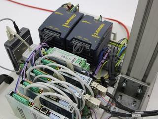
Drives and power supply


However, you cannot do much with this motors alone. A so-called drive is also required. In our case we used C1250-IP-XC-0S-000 drives. These have an Ethernet interface, which means that all communication takes place via an Ethernet bus. This has the advantage that a cycle time of 10ms can be achieved. In addition, you have relatively little wiring effort, since you can use a standard Ethernet cable, as well as a standard network card for the PC.
Furthermore, the drive requires a 24VDC supply for the logic supply and a separate supply for the power section. In our case we use 48VDC.
The 24VDC required for the logic supply come from a QUINT-PS / 1AC / 24DC / 3.5 power supply from PhoenixContact. It delivers up to 3.5 amps. For the required 48VDC two power supplies were installed and connected in series. This means that an output of up to 480 watts can be achieved.
Plate
By using a light aluminum plate, the inertia could be reduced, which in turn has a positive effect on the dynamics. Regarding the mounting, it was important that on the one hand a high degree of movement is possible, and on the other hand that the structure is as free of play as possible. The choice fell on a universal joint meeting this specification. This can be moved in all directions with almost no play. In the first try, we used a conventional one that you can find in every toolbox. However, these have way too much play. Later we decided on a special precision universal joint. With this the play is considerably smaller.
The plate itself has to meet some requirements:
- The surface must be black and as matt as possible. This is important so that the light is not reflected, which would interfere with camera detection.
- The plate must have as few bumps as possible. With such a sensitive regulation, even the smallest deviations are devastating.
- A white border must run around the plate, which will be used to calculate the current position of the plate. This is necessary to correct the detection error when the plate is inclined.
- The entire plate with the edges must be completely captured by the camera at every angle.


Our challenge was, among other things, to solve a labyrinth that can be individually constructed and then recognized and solved. Placing a wall on a plate, which at best has no recesses, is not easy. Holes are out of the question, otherwise the ball would always fall into them. If the walls are glued, it is almost inevitable that the adhesive will leave residues on the panel.
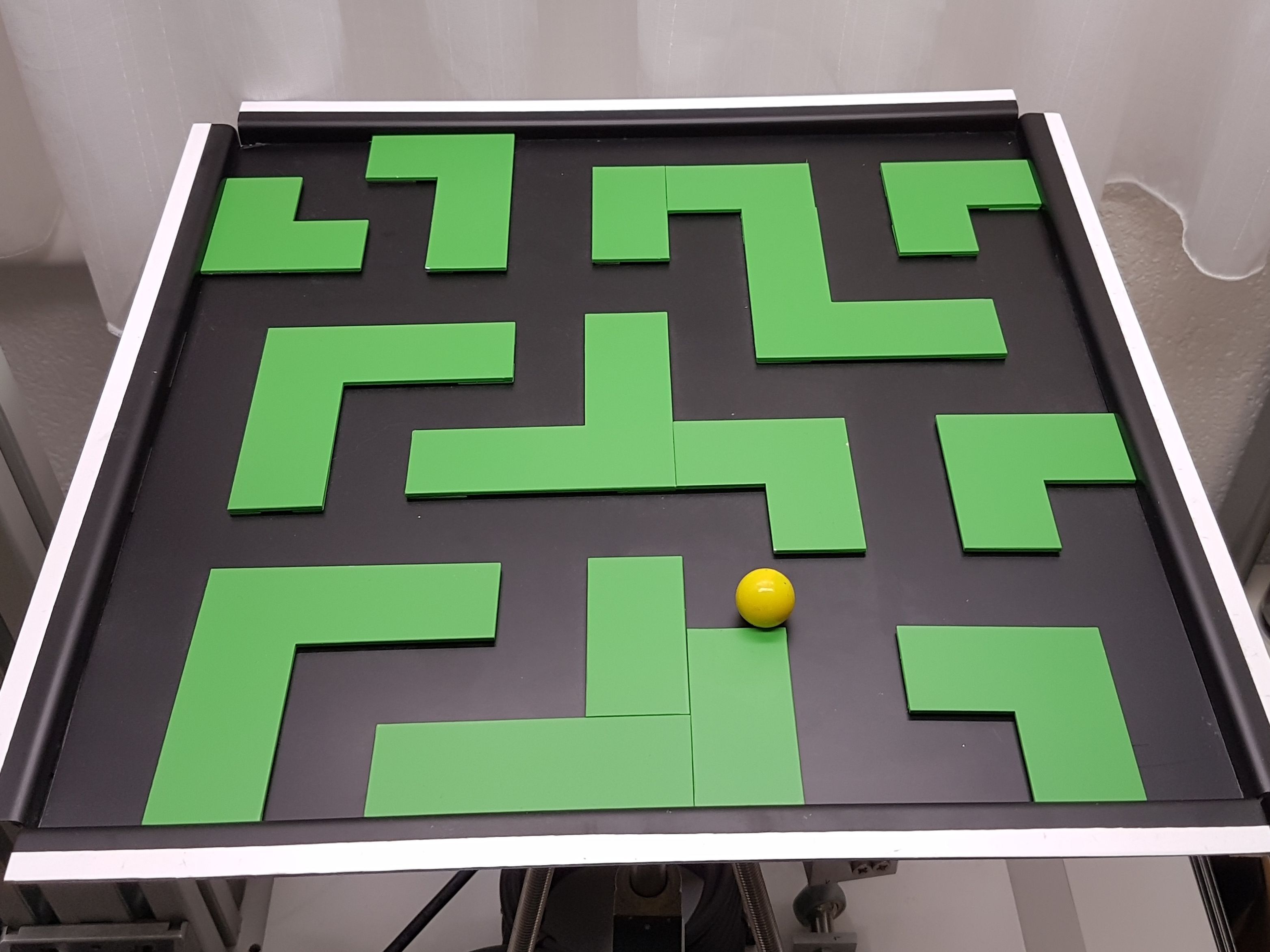
After a long search we came up with the idea of using magnets. As you can see, metal tracks are arranged in a grid pattern. This allows you to place the walls exactly and they are kept in place. On top we put a thin aluminum plate. Since aluminum is not magnetic, it does not affect the grid.
The walls are painted matt green. This helps to distinguish the green walls from the black very well. Ultimately, you have a very high-contrast picture. It was not easy to find a color that was matt so that the light would not reflect and be bright enough that the camera would be able to capture it.
Camera and lighting


To caputer the image, we used a standard webcam. In our case, the Logitech HD Pro Webcam C920, which delivers a maximum video resolution of 1080p at 30 frames per second, which is sufficient for a clean control. Due to the constant movement of the plate, the autofocus had to be deactivated. So the camera delivers a constantly sharp image. This is absolutely necessary for the position aquisition to be successful. The camera can be adjusted as desired and still offers a stable hold. It is important that the camera does not wobble even in the event of strong vibrations due to the motors. In our case, however, the construction is stable enough.
The lighting is provided by two fluorescent tubes, which generate an evenly soft light, which is well suited for camera detection. If this wouldn't be the case, even small changes in the ambient light could have a major impact, which could possibly make the entire system inoperable.
Software
The software is running on a normal PC, a powerful one though. The image processing uses a lot of CPU recources. First we thought about running the software on a spezial microcontroller which supports LabView. As things turned out, a microcontroller is by far not powerful enough to handle all this processing. Well, at least at the time we did this project. Nowadays, the situation might be completely different. The software consists mainly of four pieces:
- Demanded position: There are differente modes available:
- Sett the target position: Ball moves to this point.
- Define a way to follow.
- Maze will be recognized path is calculated.
- Position recognition and control: With the camera, the position of the ball is analyzed and depending on the actual and target position, a variable control signal with help of an PID controller is calcualted.
- Actuator control: The calculated inclination will be processed and the target actuator position is sent to the drives via ethernet.
A overview of the software can be seen in the picture below:


Main control panel


Basically, everything can be controlled here. In addition, you have an overview of all the necessary information, such as the captured position, the control deviation, the recorded images and the different cycle times. The individual modules can also be controlled or tested separately for test purposes.
Modules
The entire software was divided into various modules. On the one hand, this enables a high degree of modularity to be achieved and, on the other hand, the clarity is greatly improved. The individual modules are described below:
Capturing ball position


The process of capuring the ball consists of three steps:
- First a grayscale image is generated. This means that the colors are filtered out of the captured image, in which the colors red, blue and green are available. You can filter for specific colors. In our case it is the color yellow. This makes the ball appear very bright and the rest rather dark.
- A binary image is then generated using thresholding. Thresholding separates an image into two areas. This is called segmentation. One area contains objects, the other is the background. The grayscale values that lie within a defined level are set to 1, all others to 0. Thresholding defines areas that are of particular interest and that are to be processed later.
- Finally you search for the ball in the picture. The so-called "circle detection" function is used. With this function all round objects in the image are detected. If you now set the search to a defined diameter, it is relatively easy to find the ball. In the end, you have the pixel coordinates of the ball. However, this search function is computationally very expensive.
Determining of plate edges


Since the ball is always detected a little differently depending on the inclination of the plate, the error must be eliminated by calculation. To do this, you can determine the actual position using the affine transformation. For this you need the transformation matrix first.
In order to generate the transformation matrix, you need three corner points out of four. In our case, the upper right and left as well as the lower left corner needs to be detected. This is done as follows:
- The white border is filtered out, which then appears much lighter.
- Then the edge (from light to dark) is detected. This edge is then the X or Y coordinate.
This is done for all the designated sides. This way you get the three needed corner points.
Generating the transformation matrix


Now you no longer want the coordinate of the ball within the entire image, but within the labyrinth, or rather, within the area detected above. We give this area a grid of 400 x 400 pixels.
Through the known three corner points u1, v1, u2, v2, u3, v3, where u stands for the X coordinate and v for the Y coordinate and the target values x1, y1, x2, y2, x3, y3, in our case (400/0), (0/0) and (0/400), the labyrinth is transformed to the full image and the transformation matrix is calculated.
Calcualation of the correct position
If you now insert the detected position in a vector and multiply it by the transformation matrix, you can correct the position error caused by the inclination of the plate and get the correct position in pixels. Finally, these values have to be converted into millimeters, since the set point is also defined in millimeters. Given the resolution of 640x480 pixels used, you are able to determine the position with an accuracy of approx. 0.62 millimeters. This is fine for our requirements.
Capture the walls


To capture the walls, first a picture is taken an it is then filtered depending on the wall color. In this case, the color green is used. Then the contrast is increased. This creates a picture in which the walls are clearly visible. Then the maze is transformed to the size of 400x400 pixels with the help of the transformation matrix, so that the entire surroundings disappeared. You now have a picture that only contains the maze itself. It is divided into a grid of 13x13 fields, in which there is either a wall or not. Now every field is checked whether there is a wall. The result is finally entered in a matrix. If there is a wall, a 2 is entered, otherwise a 1.
Solve maze by use of algorithm
The fastest route through the maze can now be calculated from the generated matrix. We developed our own algorithm based on existing ones. We dealt with various approaches to the principle of the "shortest path" algorithm. We studied the function of the Dijkstra’s as well as the A * algorithm. However, to explain this here would go beyond the scope of this document. Basically, ours is a simplified form.


The entire searched structure is saved as a tree structure. This approach is based on graph theory, which can be used to represent the topology. Now you specify the starting point in the matrix. At the beginning there is only one point that has to be queried. Now all four directions are queried whether there is a free field, whether there is a wall or whether you have already been there. In order to prevent endless searching, every position visited must be marked. So you always know where to go. In the case of a possible route, only the next point is added. If there are two or even three possible paths, the next point is simply added for the latest one and a new branch is created for each further possible direction. For each run, the foremost point of every branch is queried for each branch.
The branch that reaches the target point first is therefore the fastest. This is then saved and passed on separately. You now have a list which shows the order in each fields of the maze must be traversed. For the time being, however, only the coordinates of the matrix and not the actual position values are available in the list. These are processed in the next step.
Generating the route and its execution
So far, you only have a list in which the free fields, which have to be followed one after the other, are entered. More precisely the coordinates in the matrix of the fields of the calculated route. You can't do anything with it yet. This list must now be converted into a usable route.
First, the actual points in millimeters within the labyrinth are calculated, depending on the size of the labyrinth and the grid size. So you have the center points of each free field that has to be traveled. However, this is not enough to follow a route. Therefore, a route is generated at a distance of 0.5 millimeters per point. This gives you a smooth path from start to finish, which the controller can process very well.
Now you can travel throught the route. This is done with the help of a state machine:
- Initialization: The route is read in and the starting point is output.
- Start: As soon as the start signal is present, the system begins to output point after point at a predefined speed.
- As long as there is another point, the next one is output.
- End: When the end point is reached, execution stops and the ball stops at the target position.
Position controller
The position control is realized with a PID controller. First the current position is calculated. The controller then compares the setpoint and actual value and the resulting inclination of the plate is generated. In principle, a very fast cycle time of about 9 milliseconds would be possible, mainly required for image processing of the position detection. Due to the camera with 30 frames per second, the controller is executed 30 times per second, which results in a cycle time of 33 milliseconds. A faster cycle time makes no sense, since the new position could not yet be recognized.


At a later point in time, it would also be conceivable to integrate a combination of two PID controllers. This gives you the option of generating acceleration and deceleration ramps as well as defining a maximum speed. So you can improve the control behavior again.
Driving the actuators


There are two modes here. The motors can be controlled manually for test purposes. Otherwise you can activate it for the control, which then regualtes the motors depending on the required inclination.
The motors are controlled via LinUDP. This is a UDP-based communication protocol from LinMot. In contrast to a TCP-IP protocol, no constant connection is maintained and its durability is not checked, and data transmission is also not secured, which in theory can result in data being lost during transport through the network. However, its implementation is a lot easier and with a stable network it is not a problem.
Since in our case the software has to run on a very powerful PC, due to the high computing effort for image processing, a separate network card had to be used for the connection, which guarantees an optimal and trouble-free connection. The position is transmitted every 10 milliseconds:
Final thoughts
All in all everyting works as expected, but as we know, nothing ever works right away. We had to rebuild the construction three times before our expectations were satisfied. One of the main reasons was the high dynamics of the linear actuators.
Later, as we had a well funtioning control system, we still experienced a big deviation between actual and target position. After some thinking, we detected that the ball's surface was not really smooth. We thougth we just use a glass marble. With closer inspection however, we found the reason. So we changed to balls from big ball bearings. With this upgrade, the controll system worked way better. We also struggeled with changing lighting at the beginning. But with a propper lighting source, proper color selection of all parts and fine tuned software, this turned out pretty well.
In conclusion, all our requirements were satisfied. We have a maze which is able to solve itself and autonomously control the ball to the end position. The construction is as stable as needed and yet portable. The position detection of the ball works well with an accuracy of 0.62mm. The maze can be solved in any combination, the shortest path is found every time. The position control and and autonomous driving of the ball works seamlessly no matter where the ball is.
So i guess we can be pretty happy with this project. But is it really finished? Well, like any other personal project, there is always something to modify...