Force feedback sim prototype
This one is a prototype for a forece feedback simulator. In real size there would be a seat on top of it where the person playing would sit in. What this means is, when you play a game or a simulator, the motions are reproduced on yourself. Imagine you play a racing game, when you accelerate, brake or make a turn, it feels like you are sitting in a real car.
Originally, I came up with this idea because at this time i worked in a company which produces such amazing pieces, and I had the chance go get some of the big ones for my own. But before we startet building the full size one, we wantet to try it out in small scale.
It worked out pretty well. The software is developed with LabVIEW and you can control it with just a X-Box controller. It was basically a experiment to find out how the basic mechanical construction would behave and how I can implement the algorithm to control this. Unfortunately, we diden't have the time yet to build the full size one.

Overview
Construction
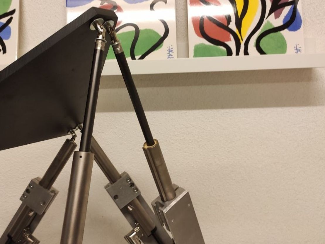
The construction is pretty simple. It's a so called "Hexapod". You have a bottem and a top plate and in between six linear actuators. The only special thing here is, it uses special high dynamic magnetic linear actuator. Regular linear actuators consists of a fixed ball nut and a rotating ball screw. With the actuators used here you can achive a very high dynamic. With regular actuators, this would be really difficult.


For the connection with both the top and bottom plate, we used some standard universal joints. This was important cause the platform moves in all three directions. This type of actuator enables a very good ration of actuator size to usable travel length.


Controller
The controller consists of six actuator drives. They control each linear actuator. The actuator itself only consists of the coils and some electronic for distance and temperature measurement. The drives have an ethernet interface which allows to connect them with regular ethernet cables and the use of a standard ethernet card for the PC. This in turn makes the wiring a lot easier.


Because this drives consume a lot of power, a 400V power suply was needed. Especially when accelerating, they need a lot of current.
Software
The complete software was made with LabVIEW. Despite I wouldn't recommend to use LabVIEW again, at that point in time however, I was pretty comfortable with it and you can do a lot of prototyping in a short amount of time. Nowadays I would probably just use Python.
First, I had to capture the input of my X-Box controller. There was allready an building block in LabVIEW which allows you to read out all your input devices. That was the easy part.
Then I had to calculate the positions of each actuator. Fortunately, you find a huge amount of useful recources in the internet under the term "Stewart Platform". I found a useful paper on the website of instructables.com. The paper itself can be found here. I'll shortly explain it here:
The Stewart Platform consists of 2 rigid frames connected by 6 variable length legs. The Base is considered to be the reference frame work, with orthogonal axes x, y, z. The Platform has its own orthogonal coordinates x’, y’, z’. The Platform has 6 degrees of freedom with respect to the Base. The origin of the Platform coordinates can be defined by 3 translational displacements with respect to the Base, one for each axis. Three angular displacements then define the orientation of the platform with respect to the Base. A set of Euler angles are used in the following sequence:
- Rotate an angle ψ (yaw) around the z-axis
- Rotate an angle θ (pitch) around the y-axis
- Rotate an angle φ (roll) around the x-axis
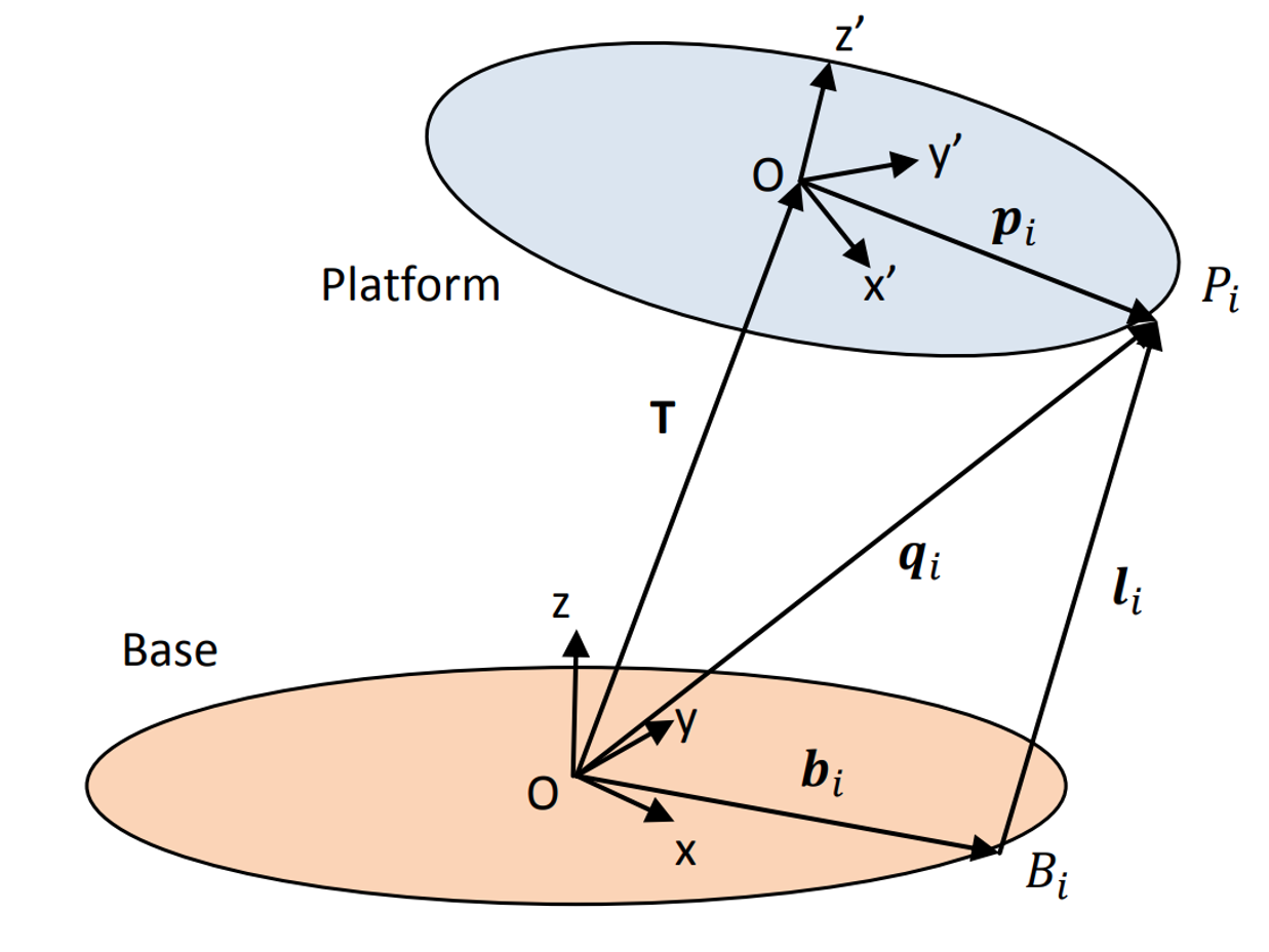
Now consider a Stewart Platform:


First we need the full rotation matrix of the Platform relative to the Base. The derivation can be found in the above refered paper:


For the "ith" leg: The coordinates "qi" of the anchor point "Pi" with respect to the Base reference framework are given by the equation:


Where T is the translation vector, giving the positional linear displacement of the origin of the Platform frame with respect to the Base reference framework, and "pi" is the vector defining the coordinates of the anchor point "Pi" with respect to the Platform framework. Similarly the length of the "ith" leg is given by:


where "bi" is the vector defining the coordinates of the lower anchor point ""Bi. These 6 equations give the lengths of the 6 legs to achieve the desired position and attitude of the platform. The vectors "bi" and "qi"can be either calculated or like in my case, as i planed this construction in CAD, just meassured.
We now have sufficient information to calculate the lengths of the effective “legs”. But to design and implement the hexapod platform we need to define the “home” position of the platform. By definition this will be where the platform is at a height "h0" above the base framework, and there being no other translational or rotational movement. This means wenn using equation 2:


Important to notice here that the initial hight can not be measured form base to platform but from the universal joint to the universal joint.
So with calculation ready, I could just control translation vector T and the rotation maxtrix with my X-Box controller and the platform was moving. With the six lengths of the legs available, I just had to calculate the effective position of the slider and send the commands each drive. This is accomplished with LinUDP. This is a UDP-based communication protocol from LinMot. I had a library for LabVIEW available, so things worked pretty smooth.
And then, it was up and running and we could finally play with it.